
Custom Parts from a Physical Sample: How 3D Scanning Works When No Drawing Exists
When a bushing, gear, or bearing housing breaks on a 25-year-old machine, the original manufacturer is often long gone, leaving you with no blueprints in your maintenance files. Guessing at dimensions causes costly line stops, but 3D scanning reverse engineering for custom parts turns your worn sample into a production-ready component with full CAD documentation.
What Happens When a Critical Part Has No Drawing?
Losing part documentation is a standard headache in busy industrial plants. You usually run into this issue when dealing with obsolete OEM equipment, missing or misplaced paper blueprints, machinery acquired secondhand, or old in-house modifications that nobody ever wrote down. When the original manufacturer shuts down or drops support for legacy models, finding a replacement through traditional supply chains becomes almost impossible. That is why obsolete replacement parts manufacturing relies on recreating custom parts from a physical sample.
Operating without engineering drawings quickly burns through your operational budget. Machine downtime drags on for weeks while your team searches online forums or places emergency calls to specialty suppliers. If you find an OEM willing to pull old parts from a vault, you often face extreme markups and massive lead times. Meanwhile, technicians waste hours trying temporary fixes, grinding stock components, or attempting repeated one-off repairs that never quite solve the core alignment issue.
Taking manual measurements with dial calipers or micrometers seems like a quick fix, but hand tools fail when dealing with complex industrial components. Calipers work fine for a simple outer diameter, but they cannot accurately map organic curves, freeform surfaces, complex gear pitches, or tight-tolerance internal bores. A small measuring error on a critical datum surface means your newly machined part will bind, overheat, or destroy surrounding components as soon as you restart the machine. Doing reverse engineering parts without drawings requires a far more precise digital approach.
How Does 3D Scanning Reverse Engineering Turn a Sample into a Part?
Taking a physical object and turning it into a precise digital model follows a proven scan to CAD reverse engineering workflow. Each stage builds on the last to ensure the final piece fits your equipment on the first try.
- Step 1, Sample evaluation: Engineers review your physical part to assess overall surface condition, identify critical mating faces, check for stress fractures, and evaluate how the component interacts with surrounding hardware.
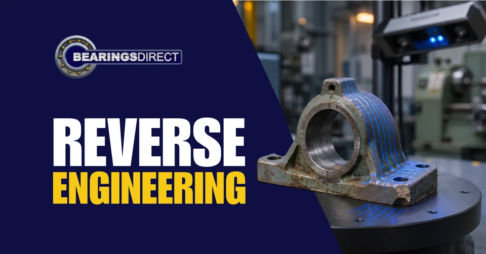
- Step 2, Scanning: Optical scanners bounce light or lasers off the part's surfaces. The system captures millions of spatial measurements, building a high-density point cloud to CAD model foundation that mirrors the sample's shape in digital space.
- Step 3, Mesh processing: Processing software filters out background noise, aligns multiple scan angles, and stitches the raw point cloud data into a clean STL mesh file.
- Step 4, CAD reconstruction: A surface mesh is only a hollow shell, so engineers use it as a guide to model a parametric solid file in STEP or IGES format. This critical step captures original design intent, smoothing out wear, fixing chips, and correcting warped edges rather than simply copying the damaged state.
- Step 5, Drawing creation: Using the solid model, engineers generate complete 2D manufacturing drawings. These documents detail exact dimensions, ISO tolerances, GD&T callouts, material specs, and surface roughness targets.
- Step 6, Manufacturing and verification: The shop produces your custom machined replacement parts from raw stock. Before shipping, quality inspectors scan the new piece and overlay the scan onto the CAD model using a color-coded deviation map to confirm accuracy.
Which 3D Scanning Technologies Are Used, and How Accurate Are They?
Selecting the right scanning equipment depends on your part's size, internal features, and required working tolerances. Achieving high 3D scanning accuracy for manufacturing requires matching the right sensor technology to the target surface geometry.
Structured light scanners project blue or white light patterns across the sample while camera sensors track pattern distortion. These systems offer fast full-surface capture and generally deliver accuracy between ±0.001 and ±0.002 inches (0.025 to 0.05 mm), making them ideal for cast housings, impellers, and complex outer geometries.
Laser line scanners mounted on portable articulated arms provide the flexibility needed for larger components, deep pockets, or heavy industrial parts that cannot move off the shop floor. Their accuracy typically spans ±0.0015 to ±0.003 inches, giving operators mobile scanning capabilities across tough factory environments.
Coordinate Measuring Machines (CMM) using physical touch probes provide top-tier precision. Touch probes physically contact key surfaces to yield measurements tight to ±0.001 inches or even ±0.0001 inches. Shops use CMM inspection specifically for precision bores, bearing seats, shaft journals, and reference datums where a fraction of a thousandth of an inch matters.
Industrial Computed Tomography (CT) scanning uses X-rays to scan straight through solid parts. It captures complex internal fluid channels, hidden voids, and internal wall thicknesses that surface light scanners cannot reach. Most legacy equipment part replication projects combine these methods, using structured light for form and CMM probes for critical fits.
How Do You Reverse Engineer a Worn or Damaged Part?
Scanning a worn, chipped, or broken part gives you an exact digital copy of that damage. If you machine a piece directly from a raw scan mesh, you end up with a brand-new component that carries the exact same wear, gouges, and play as your broken sample. Effective reverse engineering worn parts requires isolating real functional geometry from localized erosion.
To fix this, engineers focus on reconstructing original design intent. They evaluate the scanned mesh to extract nominal industry dimensions, rounding off fractional wear numbers to standard decimal or metric values. They look for built-in symmetry across flanges, bolt patterns, and gear teeth, mirroring unworn sections to rebuild damaged edges. Standard features like chamfers, fillet radii, keyways, and thread pitches are identified and replaced with clean, standardized parametric profiles.
Engineers also inspect mating hardware to guide the modeling process. By measuring a clean mating shaft or an undamaged housing bore, they can calculate correct factory clearances even if the original component is heavily scored.
When dealing with a completely fractured component, scanning multiple worn samples or separate broken fragments helps. Specialists scan each broken piece individually, then align the fragments inside CAD software like a digital puzzle to reconstruct the complete assembly. This is how engineers create custom parts from a physical sample even when the sample is damaged.
How Are Critical Tolerances and Fits Recovered Without Original Specs?
A 3D scan provides exact physical shape, but it cannot reveal what engineering tolerances were specified on a drawing lost decades ago. Recovering those tolerances requires functional engineering analysis during scan to CAD reverse engineering.
Engineers start by inferring fit classes directly from mating components and machinery functions. Precision bearing seats and rotating shaft journals receive tight machine fits defined by ISO 286 standards. For example, a press-fit bearing bore might require an H7/p6 designation to ensure a solid interference fit, while a sliding drive collar uses an H7/g6 clearance fit to prevent binding during thermal expansion.
For non-critical surfaces like outer casting walls, weight-reduction pockets, or open mounting clearance holes, engineers apply standard ISO 2768 general tolerances. This practice keeps obsolete replacement parts manufacturing cost-effective without adding unneeded machining time.
Geometric Dimensioning and Tolerancing (GD&T) callouts are added to preserve functional relationships across the part. Concentricity controls ensure rotating components stay balanced at high operating speeds. Perpendicularity and flatness callouts prevent binding across mounting faces and preserve parallel shaft alignments.
Surface finishes are measured directly off unworn areas using a contact profilometer. Engineers then assign proper Ra roughness values on the engineering drawing. A precision bearing journal might demand a smooth finish of Ra 0.8 µm (32 µin), while standard mounting faces perform well at Ra 3.2 µm (125 µin).
How Is the Original Material Identified When There's No Spec?
Getting the physical shape right is only half the battle. If you machine a heavy-load drive gear out of soft mild steel instead of an alloy grade, the part will shear apart under normal operating stress. Proper material identification for reverse engineering guarantees that your new component stands up to real operating loads.
For metal parts, shops use Positive Material Identification (PMI) through X-ray Fluorescence (XRF) or Optical Emission Spectrometry (OES). These non-destructive tests read elemental composition in seconds, telling you whether your sample is AISI 4140 alloy steel, 316 stainless steel, or 6061-T6 aluminum.
Hardness testing completes the metallurgical picture. Technicians use Rockwell hardness testers (HRC or HRB scales) across sample cross-sections. This test shows whether the metal underwent specialized heat treatment like case hardening, induction hardening, or full quenching and tempering.
For polymer components, Fourier-Transform Infrared Spectroscopy (FTIR) identifies exact plastic formulas. It easily distinguishes between Ultra-High-Molecular-Weight Polyethylene (UHMW-PE), self-lubricating acetal (Delrin), and cast nylon grades.
When original parts fail due to heavy friction, chemical corrosion, or fatigue, reverse engineering parts without drawings lets you upgrade materials. You can replace mild steel with hardened stainless steel or swap base plastics for high-wear engineered polymers to extend part service life.
What Should You Send with Your Sample to Get Accurate Results?
Sending complete information alongside your physical component helps engineering teams deliver accurate custom machined replacement parts with fewer delays.
When preparing your submission, pack the primary part along with any secondary samples you have on hand. Including mating pieces like shafts, pins, or housings lets engineers physically verify fit clearances during the model review. Include details regarding machinery make, model, operating speeds, load capacities, temperatures, and exposure to washdown chemicals or abrasive grit. Note any known failure patterns, common wear spots, or past in-house modifications.
Once the project is complete, you receive a complete engineering documentation package. This includes:
- Native 3D CAD solid models (STEP or IGES)
- Clean 3D mesh files (STL)
- Fully toleranced 2D production drawings (PDF and DWG formats)
- First article inspection and deviation reports
- Your completed, ready-to-install replacement component
You retain full ownership of these engineering files, so legacy equipment part replication in the future requires no extra setup fees or design delays.
Is Reverse Engineering Worth the Cost and Lead Time vs. Sourcing the OEM Part?
Deciding whether to reverse engineer a part comes down to balancing initial engineering investments against the high costs of extended downtime. Executing 3D scanning reverse engineering for custom parts provides a clear long-term return on investment.
While scanning and modeling involve a one-time engineering fee, that investment pays for itself quickly. Buying proprietary replacement parts from OEMs often comes with huge price markups. Once you convert your physical point cloud to CAD model data into documented 2D prints, future reorders bypass design costs entirely, costing only standard machining time. High 3D scanning accuracy for manufacturing ensures that your new part fits on the first installation attempt.
Lead times offer another major advantage. Locating obscure OEM components or waiting on overseas production batches can leave critical equipment sitting idle for months. Local scan-to-part services turn projects around in days or weeks, getting your lines back up and running fast.
To address accuracy concerns, modern reverse engineering shops run digital inspection reports before shipping. A 3D color deviation map compares the machined part against the CAD file, proving dimensional compliance before the component arrives at your plant.
Reverse engineering might not make sense if an OEM part is stocked locally, priced fairly, and delivered quickly. But when parts are obsolete, backordered, or overpriced, creating custom parts from a physical sample offers a clear financial and operational advantage.
Why Choose Bearings Direct for Reverse Engineering Custom Parts?
Rebuilding legacy components demands a manufacturing partner who understands rotating equipment, close tolerances, and power transmission assemblies. When reverse engineering worn parts, having experienced engineers evaluate your sample ensures that critical bearing fits remain exact.
Bearings Direct delivers end-to-end support for custom part projects. Our engineering team guides you from initial physical sample evaluation through scanning, material analysis, CAD modeling, and final inspection.
We bring deep material expertise across high-grade bearing steels, bronzes, specialized alloys, and engineered plastics like UHMW and acetal. Every project yields documented, repeatable results. You receive fully toleranced 2D drawings and 3D solid files with complete ownership, making obsolete replacement parts manufacturing simple for future reorders.
With reliable domestic production facilities, Bearings Direct helps you cut lead times, eliminate overseas supply chain risks, and keep your machinery running smoothly.
Frequently Asked Questions (FAQ)
1. How accurate is 3D scanning for reverse engineering industrial parts?
Modern optical and laser scanners capture surface geometry within ±0.001 to ±0.002 inches. When combined with CMM touch probing for critical bearing seats and shafts, tolerances down to ±0.0001 inches are consistently measured and maintained, providing superior 3D scanning accuracy for manufacturing.
2. Can you reverse engineer a part that has snapped into multiple pieces?
Yes. Engineers scan each broken section independently, remove digital distortion, and align the pieces inside CAD software. Using surrounding hardware measurements and standard fits, we rebuild the complete component to match its original form when recreating custom parts from a physical sample.
3. What digital file formats will I receive when the project is done?
You receive industry-standard 3D solid models (STEP, IGES), printable mesh files (STL), and fully toleranced 2D production drawings (PDF, DWG) complete with material callouts, surface finishes, and GD&T specifications for legacy equipment part replication.
4. How long does the 3D scan-to-CAD process usually take?
Scanning, point cloud processing, and CAD modeling typically take between 2 and 5 business days depending on part complexity. Total project time depends on material sourcing, heat treatment, and final machining steps for custom machined replacement parts.
5. What is the difference between a point cloud and a CAD model?
A point cloud is a collection of millions of raw spatial data points captured by a scanner. A CAD model is a solid, parametric 3D geometry built using that point cloud to CAD model workflow as a visual guide, allowing machinists to drive CNC equipment.
6. How do you figure out the material grade of a sample without paperwork?
We perform material identification for reverse engineering using non-destructive Positive Material Identification (PMI) via XRF or OES spectrum analysis to determine exact alloy compositions. Hardness testing (Rockwell HRC/HRB) and FTIR spectroscopy for plastics reveal heat treatments and polymer types.
7. Do I own the CAD files and engineering drawings after reverse engineering?
Yes. Once the engineering work is completed, you own all CAD models, STL meshes, and 2D production drawings. You can keep them in your maintenance files for future reverse engineering parts without drawings needs without paying additional setup charges.
8. Can reverse engineering improve upon an original part that keeps failing?
Yes. Reverse engineering offers the perfect opportunity to correct original design flaws. Engineers can upgrade low-grade metals to hardened alloys, increase radius sizes to reduce stress concentrations, or select wear-resistant polymers to extend part life.
9. How do you confirm that a reverse-engineered part fits correctly before shipping?
The shop inspects the finished piece using CMM probes or 3D scanners, creating a color-coded deviation map overlay against the approved CAD file. This step confirms every dimension meets specified tolerances before installation.
10. Is 3D scanning necessary for simple, symmetrical turned parts?
Not always. Simple shafts, flat spacers, or basic bushings can often be measured directly using calibrated micrometers and CMM equipment. Performing scan to CAD reverse engineering with a 3D scanner provides the most value on complex profiles, freeform shapes, gear teeth, and intricate castings.
11. Turn Your Sample into a Documented, Repeatable Part
Do not let missing blueprints or discontinued OEM parts keep your production lines offline. Whether you need to reproduce a worn bearing housing, a custom drive gear, or an obsolete plastic wear guide, Bearings Direct can transform your physical sample into a fully documented digital asset.
Contact our engineering team today to submit your sample, photos, or project details for a reverse engineering assessment and quote.